Steering System: Requirements, Purpose, Types, Power Steer
Automotive steering structures the premise of any vehicle’s movement control. It contains all parts, joints

REQUIREMENTS OF STEERING SYSTEM
The guiding framework has the accompanying necessities.
<1> Excellent mobility When the vehicle is cornering on a thin, bending street, the directing framework must have the capacity to turn the front wheels strongly yet effectively and easily.
<2> Proper guiding exertion If nothing is done to avert it, directing exertion will be more prominent when the vehicle is ceased and will diminish as the speed of the vehicle increment. Accordingly, so as to acquire less demanding controlling and better feel of the street, the directing ought to be made lighter at low speeds and heavier at high speeds.
3> Smooth recuperation While the vehicle is turning, the driver must hold the directing wheel immovably. After the turn is finished, nonetheless, recuperation – that is, the arrival of the wheels to the straight-ahead position – ought to happen easily as the driver loosens up the power with which he is turning the guiding wheel.
<4> Minimum transmission of stun from street surface Loss of directing wheel control and transmission of kickback because of street surface unpleasantness must not happen.
Reason for STEERING SYSTEM
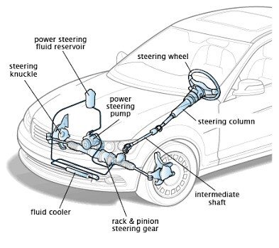
The reason for the Steering framework enables the driver to control the bearing of the vehicle by turning the front wheels. The directing framework comprises of the accompanying segment parts.
(1) Component parts
<1> Steering wheel Handles the controlling activity.
<2> Steering segment Joins the guiding haggle directing apparatuses.
3> Steering gears Convert the guiding torque and rotational redirection from the directing wheel, transmit them to the wheel through the controlling linkage, and make the vehicle turn.
<4> Steering linkage A guiding linkage is a mix of the poles and arms that transmit the development of the directing rigging to one side and right front wheels.
Additionally, there are two sorts of controlling.
• Rack-and-pinion type
• Recirculating-ball type
- Rack and Pinion
Rack-and-pinion directing is the most well-known kind of movement control component in vehicles, little trucks and SUVs.
Development
- A Rack and Pinion equip set is encased in a metal cylinder with each finish of the rack bringing up from the cylinder.
- A bar – tie bar or hub pole – associates with each finish of the rack.
- The pinion equip is joined to the directing shaft.
Instrument
When you turn the directing wheel the apparatus will turn, moving the rack. The attach pole associates with the controlling arm, which is appended to an axle.
The reason for a Rack and Pinion adapt is to change over round movement of the directing wheel into the straight movement. It permits adapt decrease, making it less demanding to turn the wheels.
The two kinds of rack-and-pinion controlling frameworks:
- End take-off
- Focus take-off
Variable Ratio Steering
A subtype of Rack and Pinion adapt controlling is Variable Ratio Steering.
This guiding framework has diverse number of tooth pitch at the inside than it has at the finishes.
This makes the directing less touchy when the guiding wheel is near its middle position.
Furthermore, when it is turned towards bolt, the wheels turn out to be progressively touchy to roundabout movement of the directing wheel.
- Re-circling Ball/Steering Box
Re-flowing Ball Steering is the most ordinarily utilized guiding framework in overwhelming vehicles.
It keeps running on Parallelogram linkage, in which:
- The Pitman and Idler arm stay parallel
- The component ingests overwhelming stun burdens and vibrations
Development
- The directing wheel is settled to the guiding shaft, which has a strung bar toward the end. The strung pole is settled, dissimilar to in the Rack and Pinion type.
- The square has equip teeth machined ON its surface.
- The strings in the bar are loaded up with metal rollers.
- These metal balls have two capacities: To lessen rubbing and wear in the apparatus; Fixing the teeth of the rigging to keep the previous from breaking contact with one another when the guiding wheel alters course.
Component
- At the point when the guiding wheel is pivoted, the pole turns.
- At the point when the wheel turns, the square moves.
- The square moves another rigging that thus moves the Pitman arm.
- The metal rollers in the strings re-circle through the apparatus as it turns.
POWER STEERING
To enhance driving solace, most current autos have wide, low weight tires which increment the tire-to-street surface contact region. Therefore, all the more controlling exertion is required. Directing exertion can be diminished by expanding the rigging proportion of the controlling apparatus. Be that as it may, this will cause a bigger revolving movement of the directing wheel when the vehicle is turning, making sharp turns outlandish. Along these lines, to keep the controlling lithe and, in the meantime the guiding exertion little, some kind of a directing help gadget ended up essential. As it were, control controlling, which had been predominantly utilized on bigger vehicles, is currently likewise utilized on conservative traveler autos.
Sort of intensity directing
There are water powered sort and electric sort control directing. At present, water powered power guiding is utilized on all models. The three principle segments of pressure driven power guiding are the vane siphon, control valve, and power chamber.
Activity of pressure driven power directing
The power directing framework utilizes the intensity of the motor to drive the vane siphon that creates the water powered weight. At the point when the directing wheel is turned, an oil circuit is exchanged at the control valve. As oil weight is connected to the power cylinder in the power chamber, the power expected to work the controlling wheel is diminished. It is important to assess for spillage of intensity guiding liquid occasionally.
Vane Pump
Power controlling is a kind of water driven gadget requiring a high weight. It utilizes the intensity of the motor to drive the vane siphon utilizes that produces this water powered weight. Vanes are utilized in this siphon, so this name is utilized for this sort of intensity directing.
Directing MECHANISMs
- Adjustable MECHANISM
The adaptive guiding component permits forward or in reverse change of the controlling wheel position to suit the driver’s stance.
Development
The adjustable component comprises of the sliding shaft tube, two wedge locks, plug jolt, adaptive switch, and so forth.
Activity
The wedge locks move together with activity of the adjustable switch. At the point when the adjustable switch is in the bolt position, the adaptive switch presses the wedge locks against the sliding shaft tube, bolting the sliding shaft tube. Then again, when the adaptive switch is moved to the free position, a hole is made between the wedge locks and the sliding shaft tube and the guiding section can be balanced in the forward or reverse way.
- TILT STEERING MECHANISM
The tilt controlling instrument permits choice of the guiding wheel position (in the vertical heading) to coordinate the driver’s driving stance. The tilt directing components are grouped into the upper support type and the lower support type. Here, the lower support type is clarified.
Development
The tilt controlling component comprises of a couple of tilt directing plugs, tilt bolt jolt, breakaway section, tilt switch, and so forth.
Task
The tilt controlling plugs turn together with the task of the tilt switch. At the point when the tilt switch is in the bolt position, the pinnacles of the tilt controlling plugs are lifted up and the plugs push against the breakaway section and tilt connection, bolting the split away section and tilt connection. Then again, when the tilt switch is moved to the free position, the tallness contrast on the tilt controlling plugs is dispensed with, and the guiding segment can be balanced in the vertical bearing.