
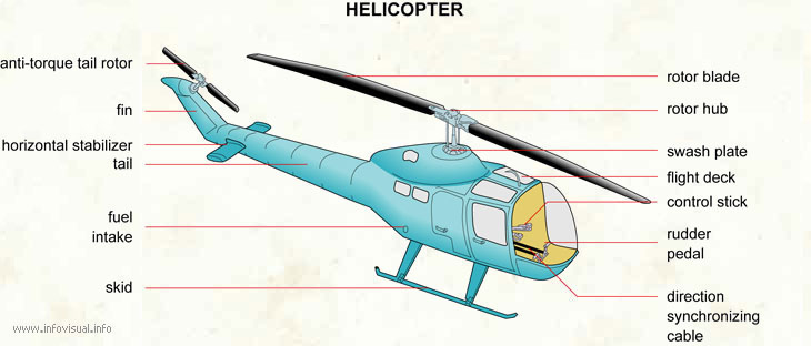
How Helicopters Fly
In basic words, helicopters are sorts of rotorcrafts in which push and lift are created with the assistance of rotors. Dissimilar to planes in which lift is produced through their expansive wings mounted sideways, rotors are situated on the highest point of the cockpit/helicopter body.
The English word “helicopter” is adjusted from the French word hélicoptère, which starts from the Greekhelix(meaning helix, winding) and pteron(meaning wing). Epithets like heli, chopper, helo, and copter are very prominent among individuals.
Turning Wing Terminology

In most helicopters, the motor turns a pole that interfaces with an information plume on the transmission; the primary rotor pole comes straight out of the highest point of the transmission and the tail rotor driveshaft associates with a yield plume 90 degrees out from the pole.
There are numerous terms related to rotating wing flight and it is critical for an understudy to get comfortable with them to comprehend the mechanics of rotational wing flight.
Principle Rotor System
Root: The internal end of the sharp edge where the rotors interface with the cutting-edge grasps.
Cutting edge Grips: Large appending focuses where the rotor sharp edge interfaces with the center point.
Center point: Sits on the pole, and interfaces the rotor cutting edges to the control tubes.
Pole: Rotating shaft from the transmission, which interfaces the rotor cutting edges to the helicopter.
Control Tubes: Push \ Pull tubes that change the pitch of the rotor’s sharp edges.
Pitch Change Horn: The armature that changes over control tube development to a sharp edge pitch.
Pitch: Increased or diminished point of the rotor cutting edges to raise, lower, or alter the course of the rotor’s push drive.
Jesus Nut: Is the particular nut that holds the center onto the pole.
Swashplate:
The swash plate get together has two essential jobs:
Under the heading of the aggregate control, the swash plate get-together can change the point of the two sharp edges all the while. Doing this increments or diminishes the lift that the primary rotor supplies to the vehicle, enabling the helicopter to pick up or lose elevation.
Under the course of the cyclic control, the swash plate get together can change the edge of the cutting edges independently as they spin. This enables the helicopter to move toward any path around a 360-degree hover, including forward, in reverse, left and right.
The swash plate get together comprises of two plates – the settled and the pivoting swash plates – which appeared in blue and red, individually.

The turning swash plate pivots with the drive shaft (green) and the rotor’s cutting edges (dark) as a result of the connections (purple) that associate the turning plate to the drive shaft.
The pitch control poles (orange) permit the turning swash plate to change the pitch of the rotor cutting edges.
The edge of the settled swash plate is changed by the control poles (yellow) joined to the settled swash plate.
The settled plate’s control poles are influenced by the pilot’s contribution to the cyclic and aggregate controls.
The settled and turning swash plates are associated with a lot of heading between the two plates. These course permit the turning swash plate to turn over the settled swash plate.
Controls:
Aggregate: The all over control. It puts an aggregate control contribution to the rotor framework, implying that it puts either “all up”, or “all down” control contributions to at one time through the swash plate. It is worked by the stick on the left half of the seat, called the aggregate pitch control. It is worked by the pilots left hand.
Cyclic: The left and appropriate, forward and toward the back control. It puts in a single control contribution to the rotor framework at once through the swash plate. It is otherwise called the “Stick”. It leaves the focal point of the floor of the cockpit, and sits between the pilots legs. It is worked by the pilots right hand.
Pedals: These are not rudder pedals, in spite of the fact that they are in indistinguishable place from rudder pedals on a plane. A solitary rotor helicopter has no genuine rudder. It has rather, an enemy of torque rotor (Also known as a tail rotor), which is in charge of directional control at a float, and air ship trim in forward flight. The pedals are worked by the pilots feet, much the same as plane rudder pedals are. Pair rotor helicopters likewise have these pedals, yet they work both principle rotor frameworks for directional control at a float.
The Tail Rotor:
The tail rotor is critical. On the off chance that you turn a rotor utilizing a motor, the rotor will pivot, however the motor and the helicopter will endeavor to turn the other way. This is called TORQUE REACTION.
The tail rotor is utilized like a little propeller, to pull against torque response and hold the helicopter straight.
By applying pretty much pitch (point) to the tail rotor edges it tends to be utilized to make the helicopter turn left or right, turning into a rudder.
Different sorts of designs do exist in which at least two even rotors are utilized to check the torque response .
Some of them are:
Couple rotors :-
Couple rotor helicopters comprise of 2 vast level rotors one mounted before the other. The principal rotor pivots clockwise while alternate turns in against clockwise bearing which disposes of the torque response.
Favorable position of this framework is having a decent longitudinal security since it has an expansive focal point of gravity extend. Couple rotor helicopters can hold more load with shorter cutting edges since they have two arrangements of rotors. Because of this capacity of conveying more noteworthy limit this config. is for the most part utilized for payload helicopters.
Drawback of couple rotor config is the perplexing transmission framework. Both the rotors are to be appropriately synchronized with the end goal that they don’t hit each other even after motor disappointment.
Co-pivotal rotors :-
In this config two rotors are mounted one over the other on concentric shaft with a similar hub of revolution pivoting in various ways. This again settle the issue of torque response and in addition it empowers the heli to expand it’s conveying limit.
Favorable circumstances incorporates expanded payload for same power conveyed by the motor; additionally the full power could be concentrated to lift and directing since there is no tail rotor(some of the power gets squandered while transmitting to it).
Drawbacks – high number of moving parts, more noteworthy mechanical intricacy and structure since one rotor must be mounted over the other along the swash plates and pitch joins.
Transverse rotors :-
Transverse rotor rotorcraft have two expansive flat rotor gatherings mounted next to each other. Like couple rotors, utilization of counter-pivoting rotors offset the other’s torque. So also, this config can hold more weight as a result of two arrangements of rotors.
Intermeshing rotors :-
Intermeshing rotors OR here and there alluded as synchopter are two arrangements of rotors pivoting in inverse directions(to invalidate torque) both mounted on the highest point of cockpit slanted at an edge. They are orchestrated in such transversely symmetrical way to such an extent that the sharp edges don’t intermesh with one another. Truly, considering the flight mechanics of these kinds of rotors would be so troublesome !!!

Nice post with adequate information..I am really thrilled about this site because it teaches the fundamental of every mechanical units parts beautifully