

intensifier is a mechanical gadget which is utilized to build the force of of the liquid. It uses the vitality of amount of fluid at weight. Some machines require high weight for working yet this high weight can’t be acquired by utilizing siphon. A portion of these machines are pressure driven press, pressure driven smash and water powered lift and so forth. These machines require high weight for this task to get the required measure of weight. A intensifier is mounted in the middle of the siphon and the working machine. It has two sorts one is single acting and other is twofold acting. Here we will talk about the main single acting water driven intensifier i.e. it supplies high weight fluid amid the descending stroke as it were. The twofold acting water driven intensifier supplies high weight in the two strokes i.e. in way. By and an ordinary intensifier can raise the weight force of fluid at 150-160 MN/.


CONSTRUCTION:
A Hydraulic intensifier is exceptionally straightforward in development; it has just three fundamental parts, these parts are joined in an appropriate succession for expanding the weight of information liquid. These three fundamental parts are settled smash, sliding chamber or slam and a settled barrel.

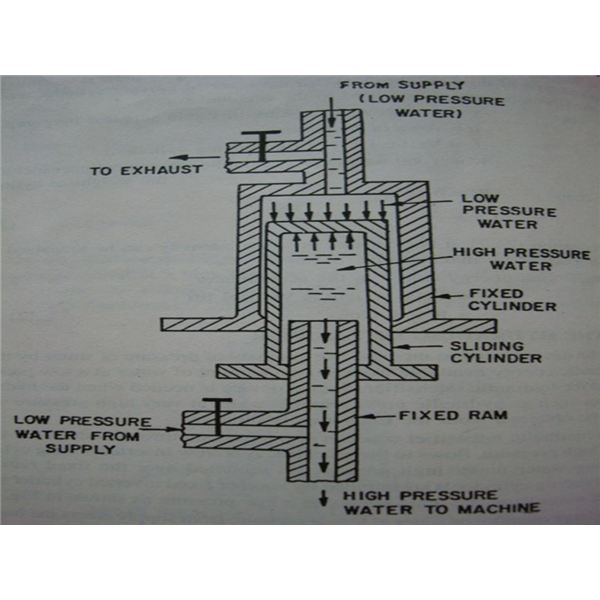
FIXED CYLINDER: It is the peripheral body some portion of the intensifier. The low weight fluid comes into the settled barrel from the principle supply. The sliding chamber or slam inside the settled barrel.
SLIDING CYLINDER OR RAM: It is the center piece of water driven intensifier i.e. it slides in the middle of the settled slam and settled barrel. This is the main moving piece of this gadget. It slides under the activity of water driven power. Sliding chamber contains high weight fluid which is provided to it through the settled smash.
Fixed RAM: It is the internal most and littlest piece of the pressure driven intensifier. It is encompassed by a sliding barrel. The high weight fluid is provided to the machine through this settled smash.
VALVES: Hydraulic intensifier comprises of four valves for simple understanding we can name them A, B, C and D. ‘An’ and ‘D’ permits low weight fluid from the supply into the gadget. The fluid roll in from valve ‘D’ goes into the settled chamber and the fluid goes in through the valve ‘A’ goes into the sliding barrel. Valve is for fumes reason i.e. it allows the low weight fluid from the settled chamber to be released to deplete. The valve ‘B’ is utilized to supply high weight fluid to the outlet of intensifier which is appended with water driven machines.
WORKING:
As talked about above water powered intensifier is utilized to build the force of liquid weight. Its working dependent on the smooth motion in it. The fluid from low weight comes in and at high weight goes out to the machine or outlet. In the beginning development the sliding barrel is at its rest position i.e. at base generally position. Presently the fluid of low weight comes into the settled barrel through valve ‘D’ and fill it legitimately. Presently the valve C, B and D are shut. The main valve ‘An’ is opened which allows the low weight fluid into the sliding barrel or slam. After that the valve ‘C’ is opened which allows the low weight fluid from the settled barrel to be released to debilitate. At the point when the low weight turns out from the settled barrel then the sliding chamber begins moving upwards because of the supply from valve ‘A’. At the point when the sliding chamber achieves the highest position then this sliding barrel is loaded up with low weight fluid. The valves ‘An’ and ‘C’ are shut when the sliding chamber totally loaded up with low weight fluid. Presently the valves ‘B’ and ‘D’ are opened, the low weight fluid from the supply i.e. through valve ‘D’ goes into the settled chamber which pushes the sliding barrel to move downwards which results high weight fluid is delivered in the sliding chamber. This high weight fluid is provided to the required yield or to the some water powered hardware. High weight fluid is turns out from the valve ‘B’. This cycle is rehashed consistently and low weight fluid turns out with high weight power.
APPLICATIONS:
hydraulic intensifier is utilized to supply high any place .
It utilized where siphon isn’t adequate to give high force of weight according to the necessity.
It is most normally utilized in water driven press, water powered smash, water powered cranes and pressure driven lifts and so forth where high force of weight is required for lift the heaps.
Advantages:
- Water powered intensifier is a smaller gadget and simple to work and control.
- It tends to be straightforwardly joined with the water driven apparatus, any place it is required.
- It is smaller and also vitality sparing gadget.
- It is less expensive gadget in the event that we looks about its working, it spare part of cash by their simple and practical activity. We can state that it is straightforward in working, sheltered and sparing in tasks.
- It has rapid activity because of this it very well may be effectively begins and stop according to our necessities.
- It can without much of a stretch works with the siphon, that is the reason it might be appended in the middle of the siphon and the pressure driven apparatus.
- It is anything but difficult to work and control.
- It gives consistent power and weight in entire working procedure.
Disadvantages:
- The primary weakness of the pressure driven intensifier is same which for the most part happens if there should arise an occurrence of the all other water driven frameworks i.e. spillage of the liquid.
- In some cases the pressure driven liquid utilized is might be destructive which harm the out hardware.
- The other primary weakness is of spillage liquid can burst into flames so the working ought to be done in legitimate way and endeavor to maintain a strategic distance from the any little spillage of the liquids.
- This framework requires high support.
- This is about water driven intensifier. On the off chance that you have any question with respect to this article, ask by remarking. In the event that you like this article, bear in mind to share it on informal communities. Buy in our site for increasingly instructive article. Much obliged for understanding it.